Geeknesia is the First Internet of Things Technology and Innovation Circuit Diagram Get creative and build your own custom smart home system with DIY home automation! Learn how to create your own smart home ecosystem using open-source platforms, DIY smart devices, and custom automation projects. Discover the satisfaction of building and customizing your smart home from scratch, and unleash your creativity to create a unique and personalized smart home experience.
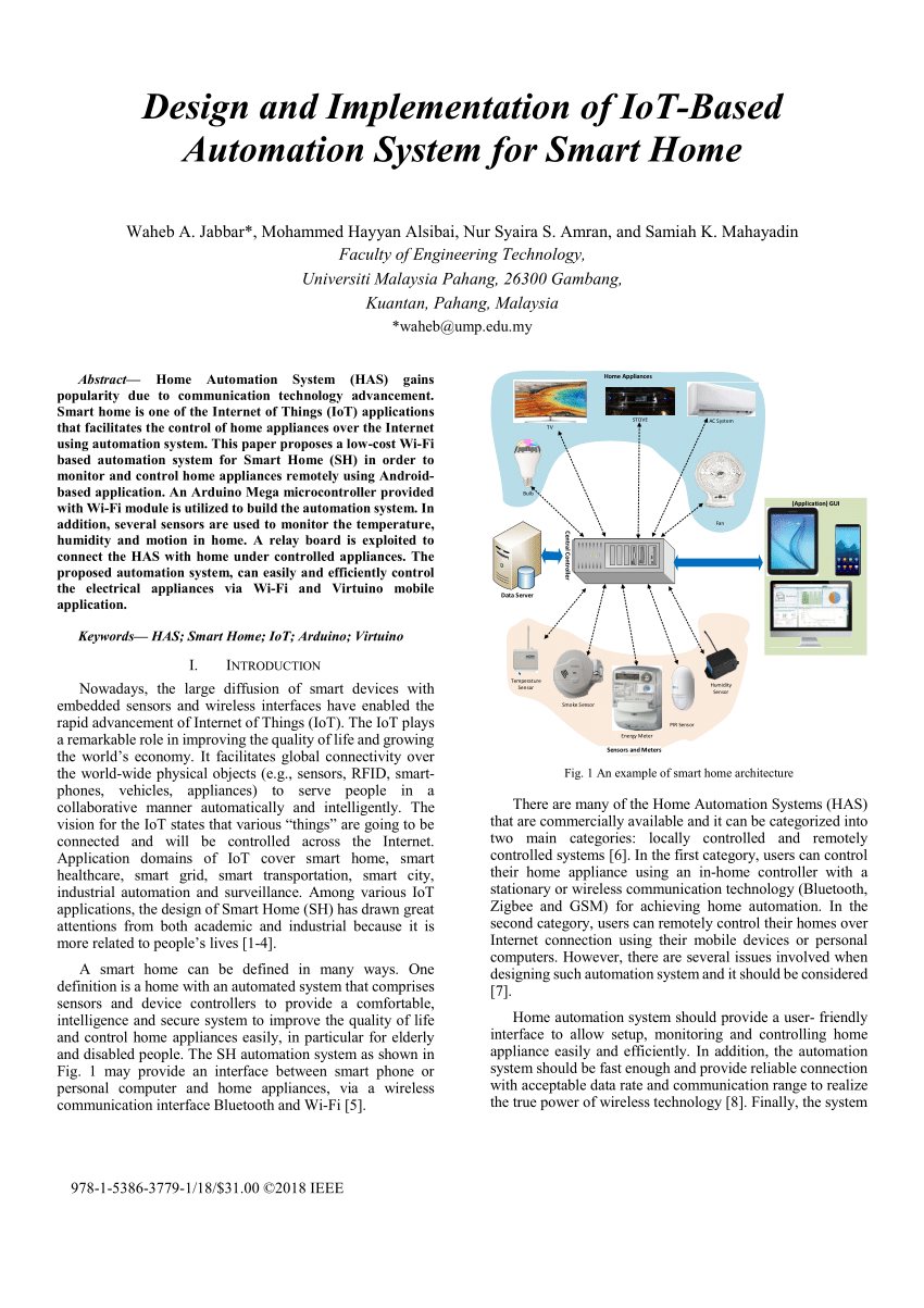
The steps involved in the designing of an IoT system or application can be summarized as shown in the below figure: Let's discuss all the ten steps in the IoT design methodology with the help of a case study: Home Automation System. 1. Purpose and Requirements Specification. First step is to define the purpose and requirements of the system. Building a smart home automation system with IoT and Python is a complex task that requires careful planning, design, and implementation. In this tutorial, we covered the core concepts and terminology of IoT and smart home automation, implemented a smart home automation system using Python and various IoT devices, and provided best practices Develop an IoT home automation system with Relevant. A home should be more than just a place to live—it should work intelligently to simplify and elevate everyday life. At Relevant, we design IoT home automation systems that don't just connect devices but create harmony between technology and your users' daily routines.
Home Automation Using the Internet of Things (IoT) Circuit Diagram
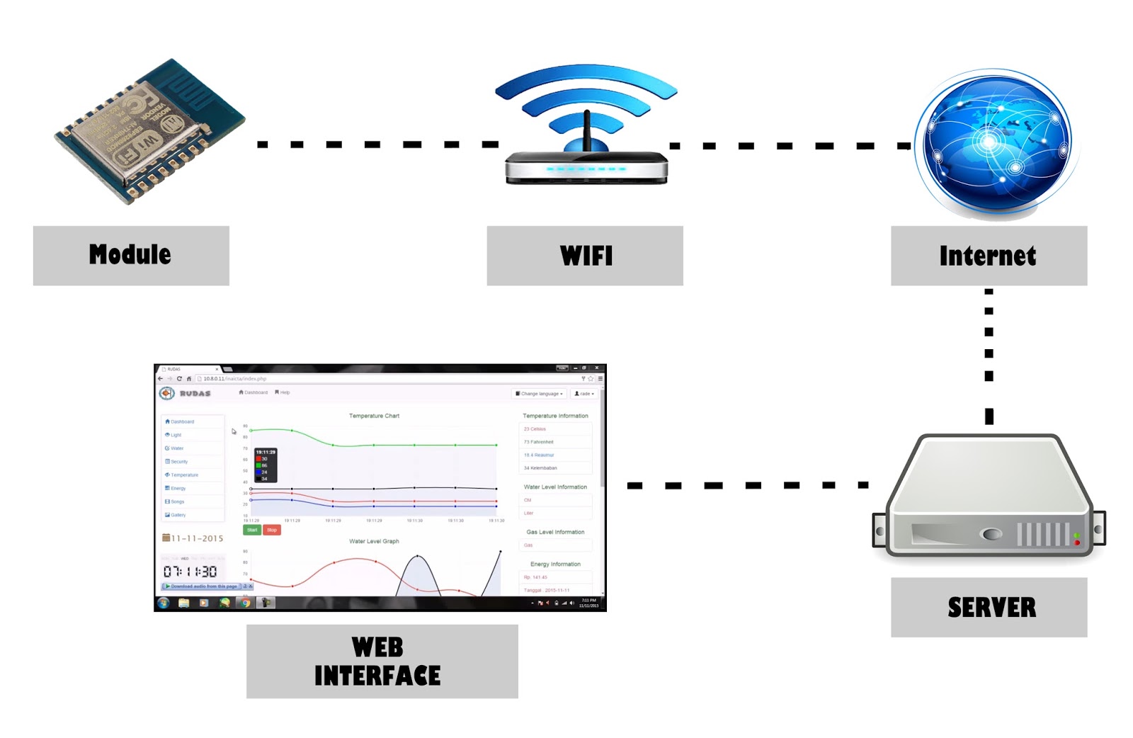
The main control chip of the smart home system connects the IoT system, sensor system and control system, obtains all sensor data in the sensor system in real time, and then processes it. The processed data is sent to the public cloud through the IoT module, and the serial port and IIC communication protocol are used to complete the reception
OpenHAB is a home automation and IoT gateway framework for smart homes. Similar to Home Assistant, OpenHAB works nicely with Raspberry Pi and comes with their own design tools to create a UI for your home automation product. An understanding architecture of OpenHAB: Modularity: It is realized with the bundle concept

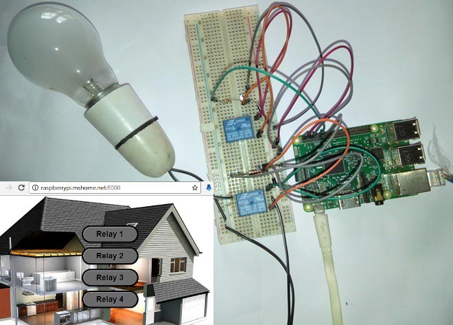
DIY Smart Home Automation: Building Your Own Custom Smart Home System ... Circuit Diagram
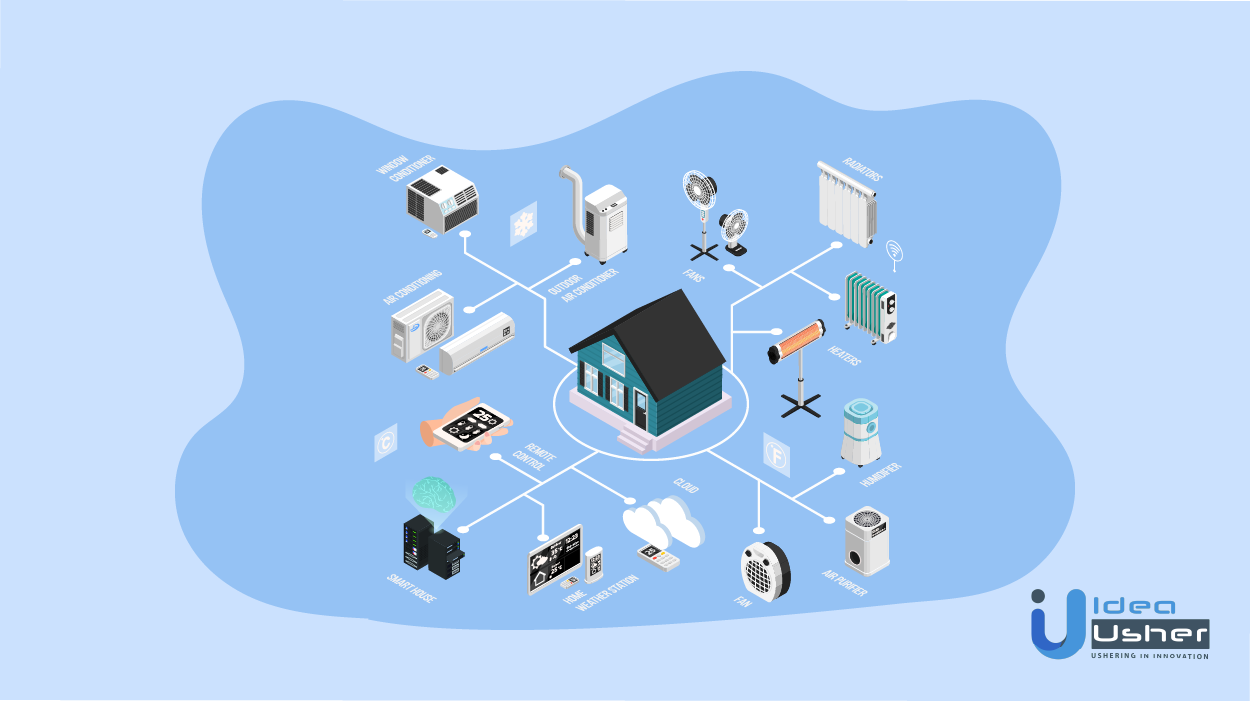
To delve deeper into the realm of home automation using IoT, we can expand the three components mentioned earlier into a more intricate 5-layer smart home IoT architecture. This comprehensive architecture provides a holistic understanding of the system's complexities and highlights the key layers that contribute to its functionality.

Creating a smart home system and an IoT system of any kind is a challenge from security, technology, and user experience standpoint. To create a successful home automation system, you need to consider many aspects, from the platform you'll be using as the base for your software to its architecture and security.