audio filter circuit Page 5 Audio Circuits Nextgr Circuit Diagram Passive Low Pass Filter for Audio Circuits (Free-Form RC Filter): One thing that has always given me trouble when making custom electronic instruments is persistent noise interference on my audio signals. I have tried shielding and different tricks for wiring signals but the simplest solution post-build seems to b…
If you're interested in electronics or signal processing, you may have heard of a low-pass filter. A low-pass filter is a circuit that allows low-frequency signals to pass through while blocking high-frequency signals. It's commonly used in audio equipment, communications systems, and power supplies to remove unwanted noise or interference.
Passive RC Filter Tutorial Circuit Diagram
Applications of passive Low Pass Filters are in audio amplifiers and speaker systems to direct the lower frequency bass signals to the larger bass speakers or to reduce any high frequency noise or "hiss" type distortion. Just want some suggestion design low pass filter circuit for my 40w-4ohms speaker as my subwoofer, thanks. Posted on

Cut off frequency of the filter will depends on the values of the components chosen for the circuit design. Cut off frequency can be calculated by using the below formula. f C = 1/ The main usage of the low pass filter circuits is to avoid A.C. ripples in the rectifier output. The low pass filter is used in audio amplifier circuits.

How to Build Audio Filter Circuits Circuit Diagram
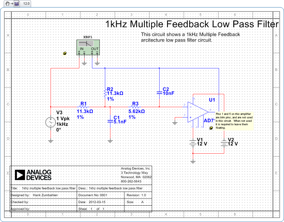
Active Low Pass Filter Example No1. Design a non-inverting active low pass filter circuit that has a gain of ten at low frequencies, a high frequency cut-off or corner frequency of 159Hz and an input impedance of 10KΩ. The voltage gain of a non-inverting operational amplifier is given as:
